|
How NC Programming can Save You Time and Money
Lets face it, today your customers want the best possible product for the lowest possible price in the least amount of time. Your job is to deliver it. While many companies struggle with this, others seem to have it mastered. There are many reasons for the successes or failures of businesses. One aspect that has helped many in the plastic industry is CNC Equipment and CAD-CAM Software.
CAD stands for Computer Aided Design, meaning that you use a computer program to design your parts. CAM is Computer Assisted Machining, which means that your computer writes the language that a CNC machine can understand (CNC stands for Computerized Numerical Control). All this means is that parts are created in the computer and the computer writes it in a language that a CNC milling machine or CNC router understands. Ultimately this process saves time and money.
Years ago I worked at a company that manufactured a balloon gift-wrapping machine. It enabled a person to put a gift inside of a balloon and was quite a novelty item. The machine, however, was very labor intensive to build. First a 2’ x 2’ piece of ABS had to be vacuum formed. Then it was taken to a band saw and cut in half, separating the top piece from the bottom. Next both the top and bottom pieces had to be placed on a cutting jig and the perimeter was hand routed. Once the bases were done they were drilled for the vacuum and exhaust holes, and several other holes needed for the power base. In all about 23 holes were drilled by hand just for the power base of this machine - this accounted for about 1/3rd of the work. In an 8-hour day it took two of us to build 17 to 20 units.
Today, CAD-CAM software and CNC machines could enable you to build 30-40 of these units a day, by yourself. With a little set up time in the beginning to program the machine the process would have been 1) Vacuum form the part (one man). 2) Place the part on the CNC. 3) Push start, return to the vacuum former to form the next part while the CNC cuts the power base and drills the holes. 4) Remove the finished top and bottom, place the next vacuum-formed part on the machine and repeat the cycle.
But you may say to yourself, "I can’t afford CNC equipment". Twenty years ago that may have been true. Today the cost of effective CNC equipment has come down considerably. For $10 - 40K you can get a machine that will cut your labor cost and give you the opportunity to take on jobs you previously may have turned down, and pay for itself in very short order.
If you are laying out templates, hand-cutting jigs with a hand-held router and then cutting parts by hand using that template, you can save time and money. Similarly if you already have CNC Equipment and are entering the information "at the controls" you could save a lot of time and money with CAD-CAM Software.
There are a number of things to look for when considering the purchasing of CNC Equipment and CAD-CAM software. Cost is obviously one of them. In today's market the price and type of equipment varies greatly. Depending on your application, you can spend from a couple thousand to $250,000 or more on equipment, and from $500 to over $20,000 on software.
When looking for CAD-CAM software, consider three things; ease of use, cost, and training. What you need the software to do should be the determining factor. Are you doing complex 3D work or mostly flat shapes? This will make a huge difference in the price you will pay. When shopping for software it helps to have prints on-hand to give to the CAD-CAM company. This will truly illustrate if their software can create the parts you plan to machine. In most cases, you do not have to spend thousands of dollars to get a package that will meet your needs. Lastly, consider whether or not the software can be easily learned or will you need to take classes or pay for training? Also find out if there are annual maintenance fees? This can be very important if you experience employee turn over. Don't get stuck with a system costing $10-20K that you can not use.

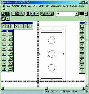
Figure 1
The part shown in figure 1 was created on a CAD-CAM software system costing less than a thousand dollars in about 20 minutes. The code was created and ready to be sent to the machine for cutting by someone who has little experience in CAD-CAM. The part we created is 48" x 96". For less than $25,000 you can purchase a reliable machine to cut a part this size and all the operator needs to do is load the material and remove the parts.
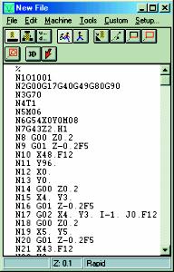
Getting into CAD-CAM software may seem intimidating at first but if you understand a few simple concepts it will make the whole process easier. Parts consist of lines, arcs and points that resemble outside shapes, holes, pockets and the like. CAD-CAM systems work with X, Y, Z coordinates. X being horizontal, Y being vertical and Z being the third plane that defines tool up tool down, or the height or depth of your part. The CAM side is where the code, or machine language, is generated. Typically these are called G-codes. While there are many G-codes, there is only a handful that need to be understood where most CAD-CAM systems are concerned. Briefly these are G00 (zero, zero). These tell the machine to go to a pre-specified clearance height and Rapid to a location. G01 is a linear move at a pre-specified speed (speeds are typically displayed in the code by an "F" for Feed speed). G02 is a circular move in a clockwise direction and G03 is circular in a counter clockwise direction. Figure 2 shows G-code for our part.

Figure 2
The shape in the illustration was created with BobCAD-CAM using a rectangle feature where you simply give the location (X and Y) of the first corner and the location of the second. The slots on the top and bottom were created the same way. The holes were located buy defining the location of the center of the hole and its radius.
The steps we took to create our G-code file are very straightforward. We set the tool up/tool down values and feed rate in a dialogue box. Then we mouse clicked on "machine", "auto", selected the line we wanted to start on and the direction we wanted to go and hit the F3 key - that tells the system to cut to the end of all connected lines and all the appropriate G-codes are written. The holes were done using "machine", "single". We now have a drawing and a file that can be saved on a 3 1/2" floppy disc with the customers’ name. It can be modified or changed at any time. There is no need to make or store templates or cutting jigs. Once you have had a little experience with CAD-CAM programming you will never go back to templates or hand routing or saw cutting that can be done with software. The quality and quantity of your finished products will increase greatly and the time it takes to get there will be less. CAD-CAM software will save you time, money, and reduce headaches.
Written by Scott Jones, VP Sales, BobCAD-CAM, Inc., manufacturers of complete CAD/CAM packages for 2/3 Axis Milling, 2 Axis Lathe, and 2/4 Axis EDM. BobCAD-CAM has been developing software for 13 years specifically for the machining of a variety of materials including plastics.
For more information, the author can be reached at BobCAD-CAM, Inc., 1440 Koll Circle, #106, San Jose, CA 95112, 800-732-3051, 408-436-7777, Fax: 408-436-7910, E-mail: bobcadsales@aol.com, Web: www.bobcadcam.com.
|