|
ROUTING: Routing Polyethylene
Polyethylene is a widely utilized plastic in the thermoforming
and sheet fabrication industry. These
manufacturing processes involve secondary routing
operations to produce the end product. Part of the
popularity of this material can be attributed to how easily
it is routed when proper cutting tools and procedures
are a part of the manufacturing process.
Plastic is generally classified as soft or hard for routing
purposes.

Polyethylene falls on the soft side of the equation
and mostly utilizes “O” flute geometry routing tools.
These tools are available in straight and spiral configurations
with single- and double-edge cutting capability. (See
Figures 2-4). The choice of straight versus spiral tooling
becomes a function of how the chip needs to be influenced.
Straight tooling has a neutral effect, while spirals
can move chips in an upward or downward direction.
 In
most instances, the thermoformer should choose straight
“O” flutes, while the sheet fabricator should rely on spiral
upcuts. When the part is held solidly, these tooling choices
accommodate the removal of chip without adversely
moving the part being routed. Most “O” flutes in the marketplace
are single-edge because they provide increased
chip clearance capability without sacrificing edge finish.
 Double-edge tools usually become a part of the routing
process when more refined edge finish is required or tool
balance is an issue.
Beside type of tool selection, tool diameter is always a
critical issue. Plastic fabricators, particularly sign makers,
tend to use small tool diameters because of small radii
and material waste considerations. However, with a softer
material like polyethylene, larger tool diameters can play
a positive role. The larger the diameter, the more flute
space is available to remove gummy chips. Also, the larger
diameter provides more stability and increased benefits fits in the area of better edge finish.
Larger diameters are beneficial, but the
end-user should be cautious in this area,
as well. Single-edge tools should never
be applied in a CNC machine in diameters
over 3/8’s of an inch. These tools in
larger sizes can create out-of-balance
issues. When larger than 3/8’s is
required, double-edge tools should be
utilized.
 These tool selection ideas are general
in nature and provide a good starting
point for decision making in this area. In
order to enhance this process, the end
user can visit www.plasticrouting.
com or any number of tooling
or manufacturing
sites to get specific
tool recommendations on polyethylene
and a variety of other plastic materials. The emphasis of this website is to recommend router tools
that provide the best finish at the most productive feed
rate.
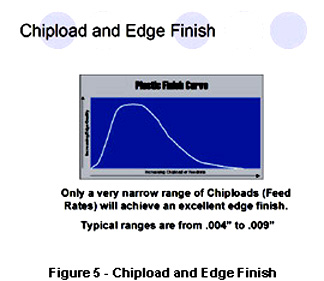
Polyethylene, like most soft plastics, will produce a
curled chip. The range of chipload to produce and maintain
a properly curled chip is somewhere between .004
and .009. Chipload is actually the thickness of the chip,
and is a function of the feed rate and the spindle speed of the CNC routing machine.
 The size of the chip has a direct correlation on the edge
finish and the ability to adequately
remove soft chips (See Figure 5). When
chiploads get too far outside the recommended
range, the tool or knife marks are
more prevalent, thus adversely affecting
edge finish (See Figure 6). Conversely,
when chiploads become too small, the
ability to clear chips without melting
becomes problematic. Consequently, it is
imperative to maintain a fairly narrow
range of chipload to maintain both of
these parameters.
Polyethylene is a
mainstay in the
plastic fabrication
industry. It is one of the easiest
plastics to cut, but only when the proper tool selections
and chipload requirements are met.
For more information, click on the Author Biography link at the top of this page.
|