|
ROUTING: Routing Polycarbonate
Polycarbonate
was commercially
developed
in the 1950’s,
and has proven to be
a versatile material
for use in the plastic
fabrication industry.
Thermoformers and
sheet fabricators utilize
polycarbonate for
a variety of applications
because of the
outstanding impact
strength and excellent
machining characteristics
of the
material.
Tooling
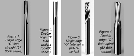
In terms of routing, polycarbonate can best be categorized
as a soft plastic. This necessitates the use of “O”
flute tools, which are distinguished by a half moon design
in the face or flute area of the router bit. These single- and
double-edged tools are manufactured from high-speed
steel for hand fed applications, and solid carbide for CNC
machinery. The high-speed steel material is only available
in straight flute configuration, while the solid carbide
material utilizes
straight and spiral
flute geometry. The
choice of straight or
spiral flute router bits
depends greatly on
how the user wants
to influence the chip.
A general rule to follow
regarding influencing
the chip is to
use “O” flute straight
or downcut spirals on
thermoformed parts
where lifting the part
can be problematic.
Sheet fabricators on
the other hand are
more concerned with chip removal, and should employ
upcut spirals with “O” flute geometry to adequately
remove chips from the workpiece. These general recommendations
can be further quantified by visiting
www.plasticrouting.com. This website, sponsored by
Onsrud Cutter, provides specific tool recommendations
based on a variety of information from manufacturers
offering polycarbonate material.
After the proper tool has been selected, there are other
considerations including rigidity and of course, programming
for the CNC user to provide a successful
routing operation. The tool selection
process can be for naught, if proper
techniques are not followed in the above
areas.
Rigidity
Rigidity is key regardless of hand fed or
CNC applications. Rigidity applies equally
to the machine itself and to the fixturing of
the components to be routed. Machine
rigidity for hand fed applications where
electric or air routers are employed mostly
involves the maintenance and replacement
of the collet system. However, the air
router requires the replacement of bearings
and spindle vanes on regular intervals
to maintain rigidity. Also, the air router
must have a minimum of 90-PSI air pressure
to maintain horsepower and it must
utilize properly toleranced tools to insure
rigidity. In CNC routing, properly lubricated
and maintained machine slides and drive
systems are essential to optimizing feedrates
and productivity. Preventative maintenance
of CNC routers is critical to long
term operation where part surface finishes
are critical.
While machine rigidity is critical to consistent
performance, fixturing is equally
important to the surface finish
on each machined part.
Fixtures should be rigidly
built and mounted to the
work surface. Vacuum supply
should be oversized
whenever possible and hard
fixturing should be securely
mounted without opportunity
for movement. When
dealing with 5-axis fixtures,
unsupported edges should
be minimized and vacuum
distribution should be maximized
at the cut area. Also,
friction enhancements such
as rubberized coatings and
gasketing sheet foam may
be utilized.

Programming
Once the tool selection
process has been finalized
and all facets of the operation
are rigid, programming the feed and speed along with
the tool path becomes paramount. The feed and speed of
the machine not only dictates cycle time, but it dictates the
creation of chipload. Chipload is the
actual thickness of the chip and is influenced
by the feed, speed and number
of cutting edges on the router bit
(Chipload = Feedrate/RPM x # Cutting
Edges). The optimum chipload to
achieve the best finish seems to be in
the range of 0.004 to 0.012. In the
case of polycarbonate or a soft plastic,
this provides the best finish by properly
curling the chips during the routing
process. The website www.plasticrouting
.com, not only provides tool selection,
but also quantifies feed and speed and
thus proper chipload for a variety of
polycarbonate materials.
Another important programming
feature is the choice of tool or feed
direction. In machining, there is climb
cutting and conventional cutting. In
most cases, conventional cutting provides
a better part, but the user
should always compare the finish of
the scrap to the finished part to identify
which edge is better. If the scrap is
better, reverse the cut direction.
Cutter entry and scrap can be particularly
problematic in routing plastic.
Plunging directly into the part gives no
path for chip removal and can cause
chip wrap, deformity or melting chips to the part. This can
be avoided by programming
the machine to
enter the part from the
side or ramp into the
part, thus providing a
path for chip removal and
avoiding all the problems
mentioned with plunging.
Scrap should be minimized
to avoid part ejection,
vibration, poor finish
and quite possibly, tool
breakage.
Polycarbonate is relatively
easy to machine
when the proper tool is
selected and good routing
practices such as rigidity
and proper programming
is utilized.
For more information, click on the Author Biography link at the top of this page.
|