|
Machining of Engineering Plastics
Engineering plastics have opened new horizons for machinery builders and design engineers.
Aside from mechanical property limitations, it has often been the case that manufacturing methods were the limiting factor for using engineering plastics. This was especially true for large volume parts made of cast nylon, acetal or PET, where other manufacturing methods such as injection molding could not be used. It was also true for complex parts which needed machining on all sides for close tolerances.
Both high precision and large volume parts can be machined economically in small and medium sized lots.
For the machining of quality, high value products, specific characteristics of the plastics must be taken into account when choosing which machinery and tooling to use and how to use it.
Machines and Tooling
No special machines are required for machining. Normal woodworking or metalworking machinery can be used with tools made with high speed steel. Saw cutting of plastic with a circular saw requires the use of carbide toothed saw blades.
An exception to this is the group of glass filled plastics. Machining with carbide tools is possible, but the short tool life does not make it economical. For glass filled plastics, we recommend the use of diamond tipped tooling which, although much more expensive than conventional tooling, have significantly longer life.
Machining and clamping the part
In comparison to metals, plastics are poor thermal conductors and have a low modulus of elasticity. If machined inappropriately, the part can heat up and thermal distortions can occur. High clamping pressure and dull tooling also cause deformation of the part during machining. The result can be dimensional variations outside of the tolerance range. Satisfactory results can only be achieved if certain guidelines are followed during machining. These are:
- The feed rate should be as high as possible.
- An optimal chip removal path should be established so that the chips do not come into contact with the part.
- The tooling should produce very sharp cuts. Dull cuts can produce heat, which can produce deformation and thermal expansion.
- The clamping pressure should not be too high, otherwise the part may deform and / or have indentations from the clamping tools.
- Because of the material’s flexibility, the part must supported as fully as possible on the machine table.
- Smooth, high quality surfaces can only be achieved if the machines are vibration free.
Cooling during machining
Generally, the use of coolant during machining is not necessary. If cooling is necessary, compressed air is recommended. This has the added advantage of blowing the chip away from the workpiece, and it reduces the possibility of the chip wrapping around the part or the tool.
Conventional liquid coolants can also be used and are recommended for drilling deep holes and for tapping. This also allows for higher feed rates and therefore shorter run times. Coolants must be completely removed from the part after machining because the oil in the coolant might cause problems in later operations such as bonding or painting. Also the water could be absorbed by cast nylon and cause dimensional changes.
Instructions for Specific Machining Methods
Sawing
Plastics can be sawed either with a band saw or a circular saw. The choice depends on the stock shape of the material. Band saws are particularly good for rods and tubes. The heat generated during cutting is drawn away by the long saw blade.
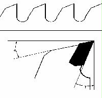
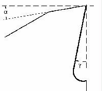
Circular saws are better suited for sheets, slabs and blocks with straight cuts. The feed rate must be high enough that the chip removal is clean so that the blade does not seize or the plastic does not overheat in the saw cut. Table 1 shows the recommended tool geometry for saw blades.
| |
Nylon, UHMW, Acetal, PET, PVDF, PVC |
| |
Band Saw | Circular Saw |
|

|
a
= Lip relief angle (o)
g
= Rake angle (o)
V = Cutting speed (fpm)
t = Number of teeth |
30 – 40
0 – 8
650 – 3,300
3 – 5 per inch |
10 – 15
0 – 10
3,300 – 11,500
24 – 80 |
Table 1: Tooling geometry for saw blades
Milling
Milling with normal machining centers is not a problem. With high cutting speeds and mid-range feed rates, good surface quality and tight dimensional accuracy can simultaneously be achieved. We recommend the tool geometry shown in Table 2.
| |
Nylon, UHMW | PTFE (Teflon) | Acetal, PET, PVDF, PVC |
|

|
a
= Lip relief angle (o)
g
= Rake angle (o)
V = Cutting speed (fpm)
s2 = Feed rate /
tooth angle (o)
|
5-15
0-15
up to 3,300
up to 0,5
0 – 40 |
10-15
15-20
up to 2,000
up to 0,5
0 – 40 |
5-10
0-10
up to 3,300
up to 0,5
0 – 40 |
Table 2: Tooling geometry for mills
Turning
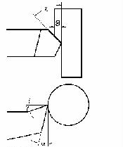
Because most plastics produce a continuous chip, a good chip removal path is especially important because it may wrap around the workpiece or the tool. Also, because plastics are not stiff, long parts may sag, and the use of a steady rest is recommended. We recommend tooling geometry as shown in Table 3.
| |
Nylon, UHMW | PTFE (Teflon) | Acetal, PET, PVDF, PVC |
|

|
a
= Lip relief angle (o)
g
= Rake angle (o)
c
= Angle of incidence (o)
V = Cutting speed in fpm
s = Feed rate inch/revolution
a = Depth of cut in inches
The tip radius should be minimum 0.020". |
5-15
0-10
0-45
650-1,600
0.002-0.020
up to 0.60 |
10-15
15-20
0-45
300-1,000
0.002-0.012
up to 0.60 |
5-10
0-5
0-45
650-1,600
0.002-0.020
up to 0.60 |
Table 3: Tooling geometry for turning tools
Drilling
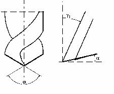
Holes can be drilled with conventional high speed steel drills. When drilling deep holes, it is important to ensure good chip removal because otherwise the hole wall could heat up the plastic to the melting point and "smear" the drill. For holes in thin walled work pieces, use a high cutting speed and a neutral rake angle (0°). This will minimize the chance of the drill catching the workpiece and tearing out material or pulling the workpiece onto the drill. Table 4 shows the recommended drill geometry.
| |
Nylon, UHMW | PTFE (Teflon) | Acetal, PET, PVDF, PVC |
|

|
a
= Lip relief angle (o)
g
1 = Rake angle (o)
j
= Point angle (o)
V = Cutting speed in fpm
s = Feed rate inch/rev.
The helix angle of the drill
should be about 12-16°. |
10-15
3-5
100 – 130
150-300
0.004-0.020 |
10-15
3-5
110 – 130
300-1,000
0.004-0.012 |
5-10
3-5
100 – 130
150-300
0.004-0.020 |
Table 4: Tooling geometry for drills
Drilling large diamter holes in round discs
Drilling large holes in high crystalline plastics such as cast nylon creates high temperatures on the drill. Plastics are poor thermal conductors, and the heat cannot be conducted away fast enough. The heat expands the material which can lead to inner stresses in the material. The stresses can get so high that the workpiece could crack. Proper machining of the part can significantly reduce this possibility. It is recommended to rough drill the hole and finish drill it with two different tools. Rough drilled holes should have a diamter of > 1.375".
With very long workpieces, holes should be drilled only from one side. When drilling from both sides, a high-stress point develops where the two holes meet, and this can cause cracking. In extreme cases, it may be necessary to heat up the entire workpiece to about 250 – 300 ° F and rough drill the hole in this condition. The finishing of the hole and the rest of the part can then take place after the piece has cooled off completely and an equal temperature throughout the material has been achieved.
If these machining guidelines are followed, complex parts made of engineering plastics can be finish machined to the highest quality standards.
For more information, contact Marc Licharz, President of Licharz Inc., manufacturers of cast and extruded nylon, and acetal copolymer shapes. He can be reached at 888-695-6662, Fax: 914-736-2154, Web: www.licharz.com.
|