|
Laser Cutting Thermoplastics
Lasers have been utilized for pointing,
engraving, welding and cutting
applications for decades. The
process for Laser Light generation, originally
known as Maser was developed in
1953 to amplify microwave signals detected
in distant stars.
 The first evidence of
Laser Light generation was in 1960 by
Theodore Maiman who successfully oscillated
a ruby with solid state control. Over
the next few years, development was rapid with the introduction
of He Ne gas (Helium Neon) laser. In 1964 Kumar
Patel invented the CO2(Carbon Dioxide) laser while
another team, J.E. Geusic, H.M. Markos and L.G. Van
Uiteit invented the Nd:YAG, Neodymium:Yttrium
Aluminum Garnet Laser. (Figure 1)
CO2 and N2 (Nitrogen) are natural found
gases that exist in our atmosphere: when
combined with He (Helium) they form the
Lasing gas in CO2 lasers. The CO2 molecule
is called the active medium and is the
source for the laser emission. Solid state
lasers utilize atoms combined with crystals
such as ruby or YAG. When doped with a
medium Cr (Chromium Ions) or Nd, they
constitute the active lasing medium.
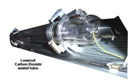
The gas laser resonator consists of a glass vacuum tube
that has a rear mirror (Figure 1) and an output coupler at the
other end; the medium is placed inside the tube. In the
case of CO2 lasers, the medium (He, N2, CO2) is sealed
within the glass tube and has a limited life span, once discharged
has to be replaced or recharged. With unsealed
CO2 lasers, gas is pumped into the vacuum tube from gas
bottles. The bottles of gas are readily available and can be
purchased ready mixed or separate per the laser needs.
There are also gas mix stations available that will mix the
gas into the appropriate proportions. A typical mix would
be 82% He, 13.5% N2, 4.5% CO2.
The wave length of laser light produced between
Nd:YAG and CO2 is used for specific material types and
applications. CO2 (typical 10.6 m wave length) is mainly
used for cutting applications in metal, plastic, wood and
with certain controls is used to engrave non-metallic materials
at high speed. CO2 Lasers have working powers up to
10,000 watts and beyond.
Lasercutting Table Types
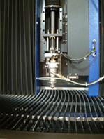
Cutting Head
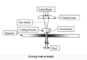
The cutting head consists of a
nozzle, lens, gas assist and may
include Z axis control. The Lens is
an important feature associated
with cutting.
 The characteristics
are usually meniscus shape and
made of Zn Se (Zinc Selenium)
with a focal length (F.L.) of 5. As
the beam passes through the lens
a hot spot is focused, (focal point,
F. P.,in this case at 5) from the
lens and is assisted with clean dry
air (or nitrogen for its cooling non oxidant properties) to carry the intensity through the cutting nozzle orifice
vaporizing the material at the point of contact. A typical
width of cut (known as Kerf Width) would be around
0.013. The position of the F.P. is important with relationship
to the material thickness and type. A normal start
point would be to set the F.P. to just sit on top of the material
surface. This is where a Z axis control is very desirable.
This is a motorized axis that allows the cutting head
to move up or down with control from a potentiometer,
software or a surface follower. It also allows the cutting
head to fully retract on job completion for ease of loading
and unloading. Z Axis control is important to ensure
 that the cutting nozzle and lens are adjustable and allow
for easy beam alignment. A typical cutting nozzle would
have a 0.060 orifice. The focused laser beam, when
passed through the cutting lens has to be central and
perpendicular to the lens, and in turn central to the nozzle
orifice. Any deviation from this would drastically affect
the quality of cut. If the beam clips the nozzle orifice, by
even 0.001, a poor quality material surface cut would be
produced that would also be out of perpendicularity.
Fixed Beam
The laser power source remains static and is mounted
onto a solid support stand.
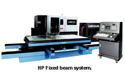 The beam delivery and nozzle
are held in a fixed position over the work area. The Laser
table moves in X and Y directions to replicate the programmed
design.
The laser beam has a fixed beam length ensuring uniform
quality cuts across the working area. This process is
excellent for
manufacturing
die
boards and provides excellent
kerf.
However, the
large foot
print takes
up floor
space. In some instances floor space
may be at a
premium. For
instance, a
system having a work area of 50x 60 would require in
excess 130 x
150, more
than double the
work area.
HyBrid Laser System
The Hybrid is similar to the
Fixed Beam but has one moving axis and one flying optic.
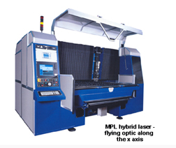 With flying optic, the laser source is usually positioned to
the side or rear of the table. The beam is guided from the
power source through a series of elbows, housing mirrors
and steered to the cutting lens position. The farther the
cutting lens distance from the power source, the greater
the beam diameter. Divergence relates to the laser beam
increasing in diameter as the distance increases between
Laser source and cutting lens. With a flying optic this
becomes critical as one mirror (axis) is continually moving
back and forth in order to cut the part. The diameter of
the beam continually increases and decreases as it passes through the cutting lens which in turn affects the quality
of the Kerf
width. Also any
slight misalignment
of the
beam as it passes
through the
90ฐ elbows, or
mechanical
looseness in the
system will
cause the beam
to change position
from the
center of the
cutting lens and
in turn move the
F. P. position, again degrading the quality of cut. A normal
control employed with a flying optic is to move the F.P.
position with the Z axis for compensation. The amount of
displacement would depend on the divergence and laser
power. The flying optic portion of the system should work
under pressurized conditions to prevent dust particles settling
on to the 90ฐ mirrors and cutting lens.
The Hybrid has a small foot print as the work table only
moves in one axis. However,
if the beam requires regular alignment to maintain a
consistent Kerf, it is usually difficult for the novice.
Flying Optics
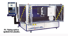 Flying Optics has the same criteria as the Hybrid, but
both X and Y have optics that move and the cutting area is
static.
It has a very small foot print, almost equal to the work
area, but is not suitable for Die making, However it is
excellent for plastics and metal cutting.
Articulated Arm
This is the ultimate
setup for
quality control
issues because
the beam length
is always consistent.
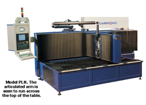 The bed is
static and renders
a footprint
equal to the flying
optics system.
As the beam exits the laser power source it is guided into a
closed pressurized hollow arm that has flexible joints. The
arm is allowed to swivel at each joint; each joint has a
beam bender mirror that reflects the laser beam from
joint to joint reaching the cutting lens with a constant
beam diameter.
This method of
control is ideal
for all applications
including
plastic, die
board and
metal cutting.
Galvo
Controlled
Marking
And
Cutting
Systems
The Galvanometer is an instrument for measuring a
small electrical current or a function of the current by
deflection of a moving coil.
 The deflection is a mechanical
rotation derived from forces resulting from the current.
This rapid deflection is used to direct the laser beam at
high speed
across a material
surface to
engrave and or
cut material.
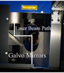
The Galvo head
consists of 2
mirrors that are
attached to
coils.
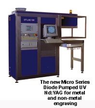 An electrical
current
excites the coils
and causes
them to orient
in the magnetic
field generated
by high power magnets. This rotation is controlled from
the programmed image via software. The laser beam
passes through a series of lenses, (dynamic focusing system)
is bounced between mirrors by the Galvanometric
action and then projected down onto the work surface. A
typical engraving speed of 7 ft per second is attainable
with working areas of 64 x 64. This principle is used with
CO2 and
Nd:YAG laser
sources. CO2 is
primarily considered
for
engraving/cutting
non-metal
material.
Cutting
Speeds
Material thickness and cutting speed has a direct relationship
to power. Increased power allows for cutting
thicker materials and for faster speeds. A typical cutting
speed chart is shown for Acrylic cutting (Figure 8).
 It
should be noted this relates to 250 and 500 watt power
sources having a polished finish and non-polished finish
speeds. Powers can be well in excess of 500 watts if
required. For 1/8 polished finish at 250 watt, and 1/8
polished finish at 500 watt, the cutting speed is the same.
This demonstrates that the process with polished finish is
speed-critical. For finished polish the speed is always
slower than non-polished finish. However, with correct
power and
speed the
acrylic surface
temperature
melts to attain a
highly polished
edge. Critical to
this process is
the need for a
quality beam
mode and a well
tuned laser. This
ensures that the
edges remain
cool enough and
not to fuse back
together. This helps in product removal and, in the case of
adhered polished parts, reduces the risk of crazing. The
advantages of using 500 watt and up is increased cutting
speed and ability to cut and polish 1 thick acrylic.
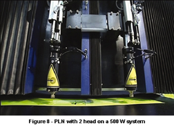
Another advantage is to have the ability to add a second
head. In the example for 1/8 acrylic, double the production
throughput by splitting 500 watts into two 250 watts
per head. (Figure 9) Gas consumption and running cost
remains unchanged with double the throughput. This is a
low cost solution for increased productivity.
To Laser Cut Or Not Laser Cut
Lasers offer many advantages when compared to conventional
cutting techniques; a quality edge finish is
achievable in a single pass, limited waste due to a thin kerf and increased productivity due to eliminated steps in fabrication.
Most materials can be laser cut, but it is always recommended
to obtain Material Safety Data Sheets (MSDS) to
ensure that the material for process does not contain
harmful chemicals that may be emitted when laser
processed (as any other thermal process). The general
guide is that PVC-type materials should not be laser
processed because of the harmful emission of Hydrochloric
Acid, the poor cut quality, having darkened to black
edges, possible damage to the machine and optics and it
is environmentally unsafe. Types of material that do not
cut well are thermosets and high temperature materials.
Epoxies, Phenolic resins and most natural rubber products
are included in this category.
Materials that cut well (thermoplastics) with laser processing
are: Acrylics, Polystyrene, Polyethylene, Polyamide
(nylon) and Polypropylene. With correct power range,
speed and good quality mode (profile of the beam), materials
can be processed in excess of 1 thick with clean polished
edges.
Cutting Speeds for Acrylic Type Material
| Nominal Laser Power | | Nominal Laser Power |
| 250W | | 250W |
| Polished Finish | | Non-Polished Finish |
|
| Thickness |
Cutting Speed |
| Cutting Speed |
|
| 1/8 |
80/min |
| 160/min |
|
| 3/16 |
40/min |
| 120/min |
|
| 3/8 |
20/min |
| 60/min |
|
| 9/16 |
15/min |
| 31/min |
|
| 3/4 |
120/min |
| 24/min |
|
| Nominal Laser Power | | Nominal Laser Power |
|
| 250W | | 250W |
|
| Polished Finish | | Non-Polished Finish |
|
| Thickness |
Cutting Speed |
| Cutting Speed |
|
| 1/8 |
80/min |
| 315/min |
|
| 3/16 |
60/min |
| 157/min |
|
| 3/8 |
40/min |
| 118/min |
|
| 9/16 |
31/min |
| 80/min |
|
| 3/4 |
24/min |
| 47/min |
|
| 1 |
16/min |
| 31/min |
Figure 9
Written by Terry Grainger, Lasercut, Inc., manufacturers
of systems for laser cutting and high speed galvanometric
marking for the plastics industry.
For more information, contact Lasercut, Inc., 69 North Branford Road,
Branford, CT 06405, 203-488-0031, Fax: 203-483-0463, E-mail: lasercut@lasercutinc.com, Web: www.lasercutinc.com.
| Return Home | Back To Top |
|