|
ROUTING: Preparing for Plastic Routing Part II
This article is the second of
a two-part series designed
to
help fabricators improve
their machining of plastics.
As companies make the transition
from the routing of
wood or aluminum to the
machining of plastics, there are a
number of preliminary procedures
and considerations that can help
ease the conversion and ensure a
smooth transition.
Periphery factors in the routing of
wood and aluminum can become some
of the most significant aspects of plastics
machining. Good planning and
preparation can help ease these factors
and the costs associated with the
startup of a new machining process.
This article is the second of a twopart
series that discusses the need to
have active preparation when making
the transition from wood routing to
plastic routing. Part 1 discussed the
CNC router and its associated hardware.
Part 2 will discuss tooling and
material selection as well as programming
considerations.
Depending on the customer’s
requirements, fabricators may have
leeway in specifying exactly what
material they will have to rout. This is
an important option and should be
taken advantage of whenever feasible
in order to reduce machining
headaches down the road.
Some plastic sheet manufacturers
produce variations of their common
sheet goods that are marketed as
having improved machining characteristics.
By all means, try these. They
typically produce better chips, do not
melt or scar as much and can sometimes
reduce the problems associated
with chips wrapping on the cutters
during plunging operations.
Various grades of the same type of
sheet can exhibit tremendously different
routing characteristics. UV protectants
can inhibit good chip formation,
fillers can cause premature cutter
wear and different sheet colors
can affect the quality of the edge finish.
Some grades may even be listed
as co-polymers. These co-polymers
may be listed as a single sheet type
but frequently contain a second plastic
in the formulation. It is better to
test cut new grades before estimating
tooling costs and routing times
because of these issues.
Another characteristic to verify
with sheet manufacturers is if the
material exhibits different machinability
going in the extrusion direction
or across it. This can be thought
of as cutting with the grain or crossgrain.
Most plastics do not react differently
in regards to extrusion direction,
but the few that do have caused
some fabricators many headaches.
Tooling Selection
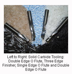
Tooling selection should be considered early during the
preparation process. While it will be nearly impossible to
 gage tool life (and therefore costs) if it is a new process
and/or material, tooling selection may greatly impact cycle
times, fixturing costs, programming needs and material
waste. Across the major tooling manufacturer’s in the
United States today,
there are more
than 90 styles of
dedicated plastic
tooling with 700 to
800 tools to choose
from. Narrowing
your choices down
to one or two tools
or styles of tools
from a particular
manufacturer can
help you determine
material removal
rates, chip extraction direction and the best diameters for
your applications. This can factor in heavily when later trying
to design fixtures and determine optimum cycle times.
Programming
The very first consideration during programming is cut
direction. For almost every plastic used by fabricators,
conventional cutting will yield a superior edge versus
climb cutting. The exceptions are typically composites or
combined materials. While conventional cutting is very
often the norm in routing (as opposed to climb cutting
during milling), nesting software that seeks to increase
raw material yield and cycle time by reducing the number
of cuts per plastic sheet can force tooling into a climb cut
configuration. If this style of software is used by fabricators,
test cuts should be made to determine whether or
not the climb cut edge finish is acceptable. If it is not, raw
material usage and cycle times need to be re-evaluated.
Another programming consideration is plunging. Many
soft plastics can exhibit severe chip wrap on the cutter
after repeated plunges. Many hard plastics can craze or
“spider web” depending on tool geometry, plunge speeds,
spindle speeds and fixture support.
The most reliable method for solving chip wrap is
ramped cutter entry. This prevents the chips from forming
in a continuous curl and will work 100 percent of the time.
Ramped entry requires special attention to the location of
entry holes and the location of nearby cut paths. Other
methods of solution involve pre-drilling of entry areas and
specially designed router bit point geometries.
Similar to soft plastics, poor plunge finishes on hard
plastics can be solved through a variety of methods.
Ramped entry will once again yield consistent finishes but
is not the only method. Craze-resistant grades of many
popular plastics are available and can withstand the
plunge pressures of standard router bits. Solid fixturing
with support directly underneath the entry point can also
improve the consistency of plunging operations. Special point geometry on cutting tools is typically the last
resort in these types of materials. The best thing to
remember when cutting holes in hard and soft plastics
is that router bits are for making traversing cuts and
drills are for making repetitive holes. The geometry of
drills is far superior to that of router bits for plunging
and they should be used whenever possible.
 A final programming consideration should be to
part fixtures. High quality, rigid fixturing methods are
essential to maintaining premium edge finishes and
there are programming methods that can enhance the
adhesion power of various hold-down methods.
In three-axis routing, a
common method of increasing
holding power is
to leave the paper masking
on sheet goods and to rout
through the plastic, but
not the bottom masking
sheet. This ensures that
the vacuum is not lost and
provides extra vertical and
lateral grip on small
pieces. Routing in this
method requires extremely
flat spoilboards and may
require frequent surfacing of the spoilboards to maintain
their surface dimensions depending on humidity
and temperature variations.
Five-axis routing programs can benefit from higher
spindle speeds that reduce the size of the chips being
formed and consequently can reduce the force being
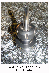
applied against the fixtures. Multi-flute tools can also be
used to achieve this benefit, but they are susceptible to
increased instances of melt and accelerated cutter wear.
The order of operations in the CNC router program
should also be examined for areas of improvements.
Small cuts and pockets should be made first to utilize
the vacuum area under scrap material. By making
large part cut-outs last, scrap material can be fixtured
the same as finished material and assist in part hold
down. Multiple depth cuts, skin cutting or tabbing can
also be utilized during programming to improve part
hold-down, edge finishes and feed rates.
Advanced planning in the areas discussed in this
article and the last article - Materials, Tooling,
Programming, Runout, Collets, Vacuum, Dust
Collection and Coolant - can help prevent some of the
common missteps that are associated with startups of
new jobs or processes. Addressing these issues can
ensure that the tools, equipment and programs are
ready for use when the job begins and that the run
costs are inline with the estimated costs.
For more information, click on the author biography at the top of this page.
|