|
AIRCRAFT FLY BY WIRE -- REAL WIRE!!
Until recently, steel cables have been the traditional means of control for all movable aircraft surfaces as well as engine speed control and other functions. And cables do not run in straight lines but do have bends and corners to traverse. Thus is the need for pulleys giving direction to the cables with minimum resistance.
Pulleys in the original flying machines of the pre-1910 era were of wood, but during WWI, increased numbers and reliability led to pulleys being machined from phenolic-impregnated fabric laminated plate. Later it became evident that a central bearing was required to minimize friction, so a graphite-loaded material was used as the bearing. After WWI, the NACA organization issued specifications for pulleys which included integral ball bearings. The initial series of pulleys were designated AN-210 with dash numbers from 1 to 10, these numbers indicating the approximate diameter of each pulley. (The AN-210-10 was a ten-inch diameter pulley used in dirigibles and blimps, not heavier-than-aircraft.
In the molded AN-210 pulleys it was necessary to provide for solidly bonding a ball bearing to the molded portion. This was solved by the use of a brass bushing molded into the pulley. After molding the cotton-reinforced sheave, the brass bushing was machined to admit the ball bearing and the brass spun over the outer race to make a solid fit. Then another operation machined the groove which would hold a cable. (Cables varied from 1/8 inch to 1/2 inch diameter and were internally lubricated during manufacture.) After machining, each pulley was sealed in moisture-proof bags.
During WWII, the Westinghouse Micarta Division produced 35,000 aircraft pulleys per week. Following WWII, more stringent requirements were made by the Defense Dept. resulting in two series of pulleys replacing the AN-210 series for new manufacture. These new ones were designated AN-219, AN-220 and AN-221. These series had more strict requirements for wear and strength. An added requirement was a "no-glow" requirement which would prevent re-ignition of gasoline vapor after a fire was extinguished. This required the addition of a boron compound. The pulleys also used aluminum bushings replacing brass to minimize weight. Unfortunately, the dimensions of the required MIL Spec. bearings did not correspond with dimensions of reasonably sized aluminum tubing. The result was the need to use heavy wall aluminum tubing resulting in much machining and waste.
Considerable reduction in cost was accomplished by the use of a "wet mix" for the molding material in these pulleys. Wet mix consisted of chopped scrap cotton fabric mixed with phenolic resin in an alcohol solution to which was added a required fire-retardant. Mixing was done in a large heated S-blade mixed, ending in a mix minus the alcohol solvent. Originally pulleys were made of impregnated cotton fabric which was then chopped into suitable squares on a paper cutting machine.
In the later 1950s, the Air Force made the MIL specifications even more stringent by requiring the molded pulleys to prevent growth by various specific molds. This required the inclusion of a fungicide in the wet mix. Resistance to standardized tests for fungus resistance was never satisfactorily accomplished. Furthermore the profit margin in molded pulleys had diminished to a point of being unattractive. Among other unattractive features of the business was maintaining a $0.5 million plus inventory of the MIL Spec ball bearings. Furthermore, it was necessary for a qualified manufacturer to make available the full line of AN pulleys. It happened that one such pulley was made of aluminum bar because of dimensional requirements. This meant that a qualified supplier of molded pulleys was forced to buy that particular item from another manufacturer. What had been a thriving business was stopped and many multi-cavity molds were carried off for scrap.
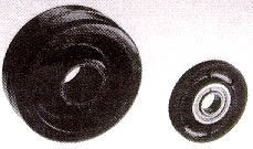
On the left is a 4-inch by 1-1/2-inch molded wheel used on industrial carts in wet and non-neutral conditions. This was molded of chopped phenolic-impregnated cotton canvas. Other sizes of wheels ranged from 3 inches to 12 inches in diameter. These were fitted with a split steel sleeve in the hub with roller bearings to contact a steel axle. On the right is an aircraft pulley, designated AN-219-5, for use with 1/8 inch control cables. The ball bearing and cable groove were the result of post molding machining.
Both pieces were molded by Westinghouse's Micarta Division.
Other manufacturers included Formica and AMCO, the latter machining pulleys out of commercially-available laminated sheets. While today's jets rely mainly on "fly by wire," even the enormous C5A uses many hundred molded pulleys. The accompanying photograph shows an AN-219-5 pulley, one of the last of the breed, made about 1960.
For more information, contact G. Marshall Naul, American Plastics History Association, 209 Glen St., Chestertown, MD 21620, 410-810-1758.
|